Ventilation flow rate testing is the on-site measurement of how much air a mechanical ventilation system is actually moving at each terminal or fan. In practical terms, it checks whether the installed system is delivering the airflow rates required by Part F, rather than just relying on what the product label or design intent said. On most residential jobs, it is the test people mean when they say a Part F ventilation test or extractor fan flow test.
Usually, yes. In day-to-day UK site language, ventilation flow rate testing, Part F testing, extractor fan testing and ventilation commissioning checks are often used interchangeably. Strictly speaking, flow rate testing is the measurement part, while full Part F commissioning also covers inspection, controls and handover information. So the airflow readings are central, but they are not the whole compliance picture on their own.
It is required because Part F is about proving adequate ventilation in the building that was actually installed, not just the one shown on drawings. Approved Document F says mechanical ventilation systems must be commissioned and, for the relevant work, measured so the results show the system is achieving the required flow rates. On site, that makes ventilation flow rate testing a sign-off issue, not a paperwork extra.
In practical residential terms, this service mainly covers System 1, System 3 and System 4. Those are the fan-based dwelling systems most clients mean when they ask for ventilation flow rate testing: intermittent extract with background vents, continuous mechanical extract, and MVHR. The current Approved Document guidance is written in functional rather than numbered language, but those industry labels are still widely used and still useful for booking and scoping the right test.
Because current common guidance in Approved Document F no longer includes passive stack ventilation as one of the standard dwelling routes it sets out in detail. Government’s 2021 response explains that passive stack can still be used if compliance is shown, but it was removed from the common Approved Document guidance because it is not common enough for inclusion there. That is why most current residential flow-rate pages focus on Systems 1, 3 and 4.
System 1 is the industry shorthand for background ventilators plus intermittent extract fans. In current Approved Document F guidance, this appears as natural ventilation with background ventilators and intermittent extract fans. In practice, that means trickle ventilators supplying background air to the dwelling and separate fan extract from wet rooms such as kitchens, bathrooms and WCs. It is the simplest and most common fan-based setup on many straightforward new homes.
System 3 is continuous mechanical extract ventilation, often shortened to MEV or dMEV depending on the setup. Approved Document F describes it as a continuous extract system that may be centralised, room-by-room, or a combination of both. In practice, it continuously removes stale air from wet rooms, while replacement air usually comes through background ventilators in habitable rooms.
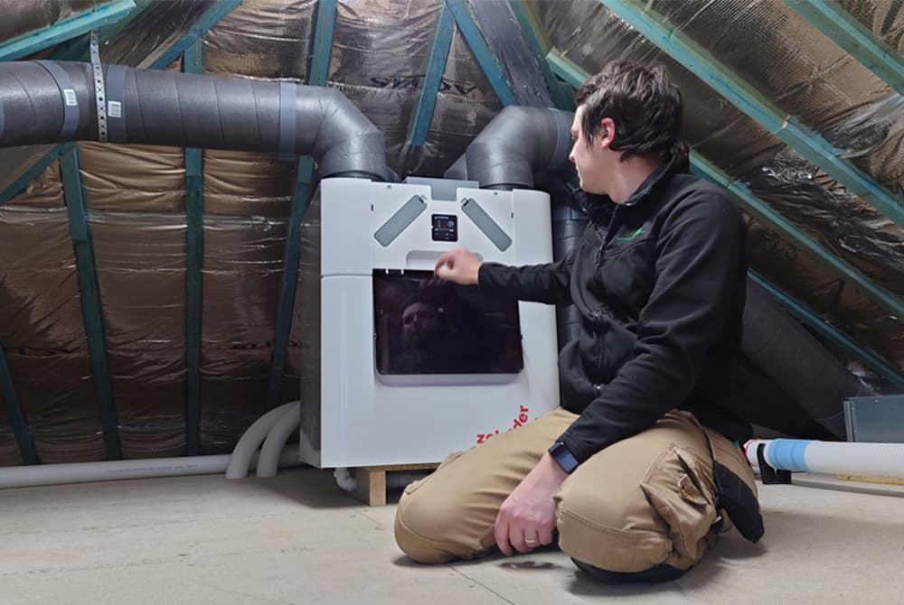
System 4 is continuous mechanical supply and extract ventilation with heat recovery, commonly called MVHR. Approved Document F describes this as mechanical supply ventilation to habitable rooms and continuous extract from wet rooms, with guidance that the moist air should not be recirculated back into habitable spaces. In practical terms, it is the whole-house supply-and-extract route used on tighter, more energy-efficient homes.
Yes. System 1 still includes mechanical extract fans, so the airflow from those fans has to be checked. Approved Document F says airflow testing applies to intermittent extract fans as well as continuous systems, and that the readings must be recorded on the commissioning sheet. The fact that the whole system is “natural plus intermittent” does not take the fan testing out of scope.
Yes. System 3 is a continuous mechanical system, so airflow measurement and balancing are central to commissioning it properly. Approved Document F says continuous mechanical extract systems should be balanced to achieve design airflow rates at each room terminal, and the measured flows should be recorded. On a live site, System 3 is not something you just power up and assume is fine.
Yes, absolutely. MVHR is a whole-house mechanical system, so both the extract and supply sides need proper airflow measurement and commissioning. Approved Document F treats continuous supply fans and terminals, and MVHR-type systems, as part of the flow-testing regime. In practice, System 4 is the route where poor commissioning is most likely to waste the benefit of a good design.
Carry it out when the ventilation system is installed, powered, and genuinely ready to commission, not while the plot is still half-finished. The core Part F logic is that the system must be commissioned and measured in its installed condition, so terminals, ductwork, controls and background ventilators all need to be in place and usable. On real jobs, calling the tester too early is one of the easiest ways to create a wasted visit.
The fans or central unit need power, the terminals need to be fitted, the ductwork needs to be complete, and the dwelling needs to be accessible enough to test properly. Approved Document F also expects the system to be inspected visually, so obvious defects, damaged ducting and missing controls are all problems before the airflow hood even comes out. Good readiness is what protects first-time pass.
Yes. The approved procedure says all internal and external doors and windows should be closed when the airflow measurements are taken. That matters because open doors or windows can change the pressure relationships in the dwelling and distort the readings. On site, this is one of the simplest setup rules, but it is also one of the easiest for trades to get wrong if the test is not controlled properly.
Yes. The approved procedure says all intended background ventilators or other air transfer devices should be open during the flow-rate measurement. That is especially important on System 1 and System 3 jobs, where the fans are meant to work with purpose-provided air inlets. Closing trickle vents to force a better reading is not a real pass; it just produces the wrong test condition.
Yes. Internal air transfer matters because the system still has to move air through the dwelling, not just at the fan face. Approved Document F says internal doors should allow air to flow through the home by providing a free area equivalent to a 10mm undercut in a 760mm door. If the transfer path is blocked, the measured room performance and the real in-use performance can both suffer.
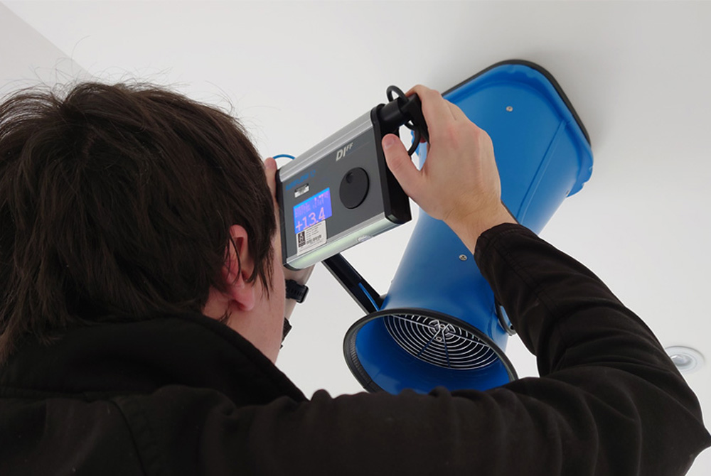
The standard tool is a calibrated airflow measurement device with a proprietary hood fitted over the terminal or fan. Approved Document F is explicit on this point, and for larger or more complex domestic systems the hood-based method is the normal compliance route. In practical terms, proper flow-rate testing is a measured commissioning exercise, not just putting a hand near the grille and guessing.
Yes. Approved Document F says the airflow device should be calibrated within the last 12 months at a calibration centre accredited by UKAS, and Wales states the same basic expectation. That matters because these are compliance measurements, not rough site checks. If the kit is not properly calibrated, the result is much harder to rely on when Building Control wants evidence.
For intermittent extract fans, yes in some cases, but not as the general answer for whole-system commissioning. The incoming 2026 England guidance says a vane anemometer may be used as an alternative for intermittent extract fans, while powered flow-hood measurement remains the preferred route for continuous systems. In practice, whole-house System 3 and System 4 commissioning still points you toward the proper hood-based setup.
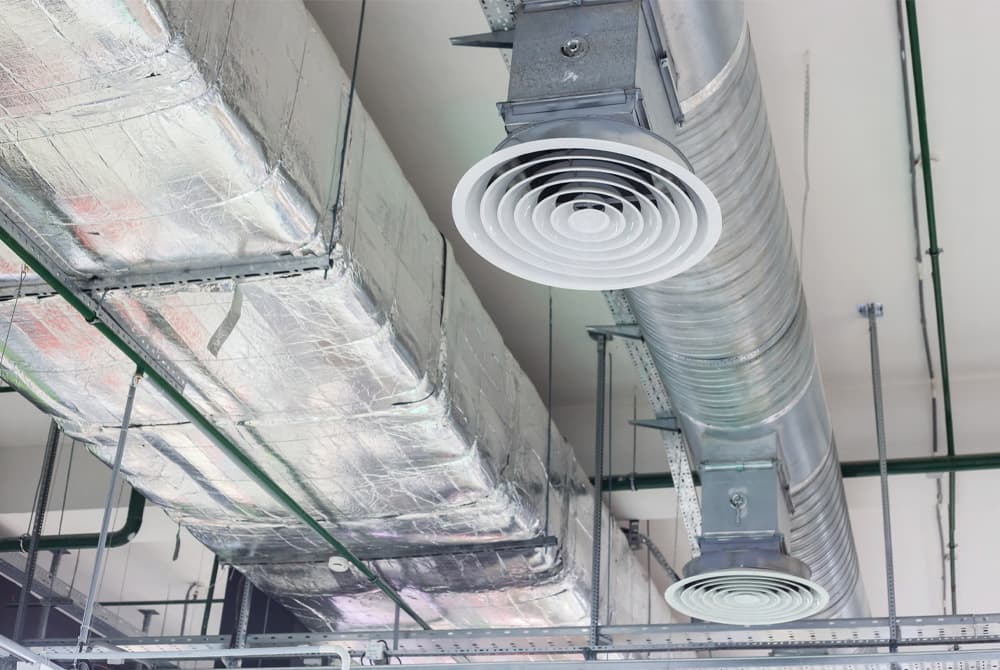
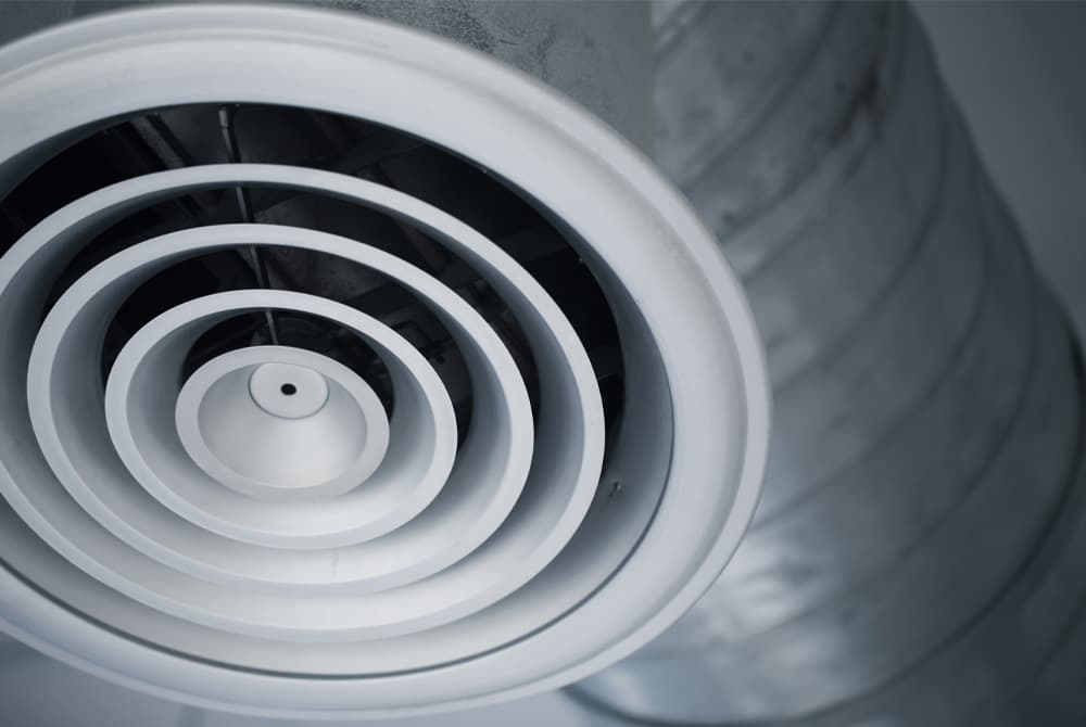
You test at each relevant room terminal or fan point, not just once at the main unit and hope the branch layout is correct. Approved Document F says the airflow should be measured at each room terminal and recorded on the commissioning sheet. That is particularly important on System 3 and System 4 because the whole point is to prove the rooms are getting the airflow they were designed to get.
Yes. Approved Document F says airflow testing includes cooker hoods as well as intermittent extract fans and continuous systems. That catches some site teams out because cooker hoods often get treated as a kitchen fitting rather than a Part F item. For compliance purposes, if it is providing extract ventilation, it is part of the testing conversation.
No. Approved Document F is clear that a recirculating cooker hood on its own does not provide a means of ventilation that complies with Part F. That is why the kitchen extract requirement changes depending on whether the hood actually extracts to outside. On site, this is a common misunderstanding that can create a late compliance problem in otherwise tidy kitchens.
For System 1 intermittent extract, the key minimum rates are 30 l/s for a kitchen where the cooker hood extracts outside, 60 l/s where it does not, 30 l/s for a utility room, 15 l/s for a bathroom and 6 l/s for sanitary accommodation. These are the baseline Part F numbers the fan test is checking against for intermittent operation.
Because the required rate depends on whether there is a cooker hood extracting directly to outside. Approved Document F sets 30 l/s where the hood extracts outside and 60 l/s where there is no external extract or the hood does not extract outside. In practical terms, the building has to make up for the missing direct-to-outside cooker extract somehow, and that is why the fan target doubles.
For the continuous systems, the minimum high-rate extract figures are 13 l/s for a kitchen, 8 l/s for a utility room, 8 l/s for a bathroom and 6 l/s for sanitary accommodation. These are the same high-rate wet-room benchmarks used for both continuous mechanical extract ventilation and MVHR-type systems. They are the key room-by-room boost numbers the commissioning process checks.
For both System 3 and System 4, the whole-dwelling minimum is the larger of 0.3 l/s per m² of internal floor area and the bedroom-based rate in Table 1.3. The bedroom values are 19, 25, 31, 37 and 43 l/s for one to five bedrooms, with 6 l/s added for each extra bedroom beyond five. That is the whole-house benchmark before you even get into terminal-by-terminal balancing.
In practice, you compare two figures and use the higher one. Approved Document F says the dwelling has to achieve at least 0.3 l/s per m² of total internal floor area, and also at least the minimum rate set by bedroom count. That means a larger but low-bedroom property can still need a higher airflow because of its floor area, not just because of its room count.
Yes. Approved Document F says that where continuous mechanical extract ventilation is used, background ventilators should not be in wet rooms, should provide at least 4,000 mm² equivalent area for each habitable room, and should be provided in a total number equal to the number of bedrooms plus two. In simple terms, System 3 still needs designed supply air paths.
For natural ventilation with intermittent extract, Approved Document F Table 1.7 sets typical minimum equivalent areas of 8,000 mm² for habitable rooms and kitchens in multi-storey dwellings, 10,000 mm² in single-storey dwellings, and 4,000 mm² for bathrooms where relevant. The dwelling also needs a minimum overall number of ventilators, not just one oversized vent somewhere convenient.
Yes. Approved Document F says that if fans and background ventilators are fitted in the same room, they should be at least 500mm apart. That spacing helps avoid short-circuiting the air path and undermining the way the room is supposed to ventilate. On real jobs, it is a small coordination detail that is easy to miss during second fix.
No. Approved Document F says that where continuous mechanical extract ventilation is used, background ventilators should not be in wet rooms. The supply air is supposed to come through habitable spaces and transfer across the dwelling before being extracted from kitchens, bathrooms and similar rooms. Putting the vent in the wet room defeats that intended airflow path.
No. Approved Document F says background ventilators should not be installed with mechanical ventilation with heat recovery, because they create unintended air pathways. System 4 is designed to provide the supply and extract air mechanically, so adding trickle vents undermines the controlled whole-house strategy. On site, this is one of the cleanest practical differences between System 3 and System 4.
Yes. MVHR is not just an extract test. Approved Document F requires testing of continuous supply fans and terminals as well as extract points, and the commissioning sheet includes separate sections for extract and supply measurements for MVHR. If only the extract side is being measured, the commissioning picture is incomplete.
Yes. Approved Document F says continuous mechanical ventilation systems, such as MEV and MVHR, should be balanced to achieve design airflow rates at each room terminal. That is why whole-house commissioning takes longer than a simple fan spot-check. On a live site, balancing is where you turn a nominal system into one that actually performs room by room.
Yes, where the guidance calls for it. Approved Document F says automatic controls for intermittent extract should have a manual override, and where a room has no openable window the fan should continue to operate for at least 15 minutes after the room is vacated. The commissioning checks also include confirming that run-on timers are set appropriately.
Not generally. The current dwelling guidance says natural ventilation with background ventilators and intermittent extract fans is suitable only for less airtight dwellings. Continuous mechanical extract ventilation and MVHR are the common routes for all dwellings, while System 1 is specifically limited by airtightness assumptions. That is why flow-rate testing and airtightness strategy should never be treated as separate worlds.
Under the current Approved Document F definitions, a highly airtight dwelling is one with either a design air permeability below 5 m³/(h·m²) at 50Pa or an as-built air permeability below 3 m³/(h·m²) at 50Pa. That threshold matters because it affects whether the natural-ventilation guidance is appropriate or whether a more controlled mechanical route should be used instead.
Approved Document F says that if a dwelling designed for natural ventilation turns out to be highly airtight when tested, expert advice should be sought or a continuous mechanical extract ventilation system should be installed following the relevant guidance. In practice, that is exactly why Part F and Part L coordination matters. The air test can force a ventilation rethink if the original strategy was too optimistic.
No. The airflow readings are vital, but Part F also requires proper commissioning, visual inspection, control checks and owner information. Approved Document F sets out inspection standards for background ventilators, ductwork, terminals and controls as well as the measured airflows. So a project can have a flow number on paper and still not have a complete, sign-off-ready ventilation package.
Yes. Approved Document F says the correct operation of control functions should be tested where practical, and it expects commissioning results to show that the system and controls are working as required. That means a proper ventilation visit is not just a hood over the grille. It is also a check that the system starts, boosts, runs down and hands over in a way the occupier can actually use.
The person carrying out the building work is responsible for ensuring the testing is arranged, but the measurement itself should be done by someone competent in Part F commissioning using the right calibrated equipment. The Approved Documents also recognise competent person self-certification routes for relevant work. On practical jobs, the safest route is a specialist who understands both the airflow measurement and the wider commissioning paperwork.
For the applicable work, the results and the data they are based on have to be recorded in the approved manner and given to the Building Control body within the required timeframe. Approved Document F says the airflows should be recorded on the commissioning sheet in Appendix C, and for new dwellings the airflow notice has to be given no later than five days after the final test.
Yes. Approved Document F says a copy of the completed commissioning sheet should be given to the owner, along with enough operating and maintenance information to use the system effectively. For new dwellings, the Home User Guide should also include non-technical ventilation advice. That handover piece matters because a well-tested system can still perform badly if the occupier is not told how to use it.
It depends on the jurisdiction and the type of work. In England’s current 2021 guidance, the specific airflow-result notice is tied to new dwellings, although mechanical systems installed in new or existing dwellings still need testing and commissioning where adjustment is possible. In Wales, the 2022 guidance says airflow rates must be measured for new dwellings and notifiable ventilation work in existing dwellings. England’s 2026 edition, which takes effect in 2027, adds clearer flow-testing guidance for certain existing-dwelling situations.
They are separate tests, but they are closely linked. Air pressure testing measures uncontrolled leakage through the building fabric, while ventilation flow rate testing measures the purpose-provided ventilation system. Approved Document F uses airtightness thresholds to decide whether natural-ventilation guidance is appropriate, and it also notes that MVHR efficiency improves as the dwelling becomes more airtight. Build tight, ventilate right is not just a slogan; it is how the two compliance strands fit together.
Cost usually depends on scope rather than one universal rate. Current UK market guidance shows very basic guide pricing from around £45 and typical pricing often starting around £40–50 per fan, but a full System 3 or System 4 commissioning job usually costs more because there are multiple terminals, balancing time and more paperwork involved. In practice, fan count, property size and whether it is a whole-house MEV or MVHR job drive the real price.
There is no fixed statutory turnaround from the consultant, but fast reporting is the normal market expectation because the results often sit on the handover critical path. Current UK provider pages commonly advertise 24-hour or next-working-day certification once the test is complete and valid. On live projects, dependable turnaround matters just as much as the site reading.
Most ventilation flow rate tests fail for practical reasons, not mysterious ones. Common causes are crushed or badly routed ductwork, terminals set wrongly, missing or closed background ventilators, power or control issues, and systems that were never properly balanced. Approved Document F’s inspection list also points to defects, wrong air direction, abnormal noise and poor installation quality as issues that affect performance. In simple terms, poor workmanship shows up quickly in the readings.
System 1 commonly falls down on the wrong fan rate, missing or undersized trickle vents, and cooker hoods that do not actually extract outside. System 3 usually fails because the system has not been balanced or the background vents are wrong. System 4 often fails where supply terminals were not commissioned properly, background vents were wrongly left in, or the duct layout creates too much resistance. The underlying pattern is always the same: the installed system does not match the design intent.
Pass first time by treating ventilation as a commissioned system, not a last-day certificate. Make sure the right system type was chosen for the dwelling airtightness, install the terminals and ductwork properly, leave background ventilators in the correct state for the system, balance System 3 and System 4 properly, and only book the test when the plot is genuinely ready. The projects that pass cleanly are usually the ones that coordinate Part F, airtightness and handover from the start.
Videos for ventilation flow rate testing
Explore our videos for quick, engaging insights on building compliance. From step-by-step guides to expert advice, our video library simplifies complex topics, making it easier for you to take action and stay informed. Perfect for when you need clarity in minutes!