
Interstitial Condensation and Mould: Cardiff Case Study
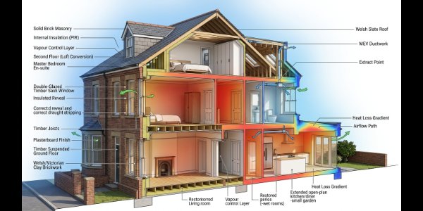
The result
A terrace conversion in Cardiff was heading for the same condensation and mould that had already shown up in the developer's previous property, three weeks before the same build up was due to go back up next door.
ATSPACE checked every build up for interstitial condensation, modelled the junctions for surface condensation, and tested the ventilation until it passed. Three junctions came back below the critical temperature factor for dwellings. All three flats completed on programme, with nothing reported twelve months later.
Project snapshot
Service: Condensation risk assessment, thermal bridging calculations and PSI values, U value calculations, diagnostic air leakage testing, ventilation flow rate testing Client: Small residential developer, four to six units a year Site address: Victorian terrace conversion, Grangetown, Cardiff CF11, full address withheld Building type: Three storey mid terrace converted into three self contained flats, 138 m² gross internal area Existing fabric: 225 mm solid brick with dense internal plaster, joists built into the outer leaf, suspended timber ground floor, cold roof void over the top flat Upgrade works: Internal wall insulation, new windows, continuous mechanical extract ventilation, new separating floors Programme stage: Pre start on the second property, post fail on the first ATSPACE delivery: Interstitial and surface condensation analysis, fRsi and PSI values, U value calculations, marked up insulation and vapour control line, diagnostic smoke testing, ventilation flow rate testing, sound insulation testing Team: ATSPACE building physics team + air leakage and ventilation testers
Why solid wall conversions carry more condensation and mould risk than new builds
Conversions fail on junctions and assumptions, not on the quality of the insulation itself. Challenges include:
- solid brick walls that cannot take external insulation on a street elevation
- joists built into the outer leaf, leaving cold bridges that cannot simply be removed
- insulation lines that stop dead at party walls and window reveals
- vapour control layers cut through by later trades, which is where interstitial condensation starts
- ventilation sized on paper but never routed on a drawing
- a cold roof void that loses its eaves gap once insulation goes in at ceiling level
The developer wanted the second property to avoid the mould that appeared in the first, without losing the original brick and bay detailing at the front.
What ATSPACE was asked to do
- carry out a condensation risk assessment before the internal wall insulation went up
- separate the interstitial risk from the surface risk, and put numbers on both
- set a ventilation strategy that would pass a flow rate test first time
- produce evidence suitable for building control and handover
- keep all of it inside a live programme
What ATSPACE did
Step 1: Evidence first, not assumptions
Only the inputs that actually move condensation risk were gathered:
- confirmed wall, floor and roof build ups, retained and new
- confirmed insulation thickness, type and where the line stopped
- confirmed window positions and reveal detailing
- confirmed the ventilation strategy and the duct routes
- recorded where joists were built into the outer leaf
Step 2: Interstitial condensation, build up by build up
Interstitial condensation happens inside the construction, out of sight, where warm moist air meets a cold layer and reaches dew point. On internal wall insulation it is the layer between the insulation and the old brickwork that matters, because the brick is now colder and wetter than it was before.
Every build up was assessed to BS EN ISO 13788, front wall, rear wall, party wall returns, ground floor and the cold roof void. The original detailing, with no continuous vapour control layer, showed moisture carrying over from one year to the next. The revised build up cleared within the annual cycle. U value calculations were redone alongside, so the fabric numbers and the risk numbers matched.
Step 3: Surface condensation, junction by junction
A wall can hit a good U value and still grow mould at the reveal. Each junction was modelled to BS EN ISO 10211 through thermal bridging calculations and PSI values, and the temperature factor, fRsi, pulled out for each one. For dwellings the critical value is 0.75, from BRE Information Paper IP1/06.
Three came back under it. Ground floor to wall at 0.68, window reveal at 0.71, intermediate floor at the joist ends at 0.72. All three sat in the exact spots where the mould had appeared next door.
Step 4: Condensation ventilation, designed then proved
Ventilation was set against Approved Document F Volume 1, 2022 edition, in force in Wales from 23 November 2022. A one bedroom dwelling needs 19 l/s whole dwelling, with continuous extract high rates of 13 l/s at the kitchen and 8 l/s at the bathroom.
Then it was checked on site. Diagnostic air leakage testing with smoke testing showed air pouring out of the ceiling void at every joist end, straight into the party wall cavity. Moving air carries moisture into cold construction and pulls local surface temperatures down, so leakage and condensation get solved together or not at all.
The main issues ATSPACE resolved
Issue 1: Window reveals left bare to keep the architrave lines
An uninsulated reveal modelled at fRsi 0.71, below the 0.75 critical value for dwellings, in the same position mould had appeared next door.
Fix: Thermal bridging calculations and PSI values put a number on the reveal before anything was built, and 20 mm insulated board to head, jamb and cill lifted it to 0.82.
Issue 2: Joist ends open into the party wall
Air was moving through the intermediate floor zone into the party wall cavity, dragging surface temperatures down below what steady state modelling predicted.
Fix: Diagnostic air leakage testing with smoke testing located every path, and air leakage on site design advice set out the sealing detail for the trades on one page.
Issue 3: Condensation ventilation ducted on site rather than on a drawing
Two of six terminals came in under the Approved Document F high rates, both from duct routing rather than fan selection.
Fix: Ventilation flow rate testing found both on the first visit, and a retest confirmed every terminal after the routes were corrected.
Outcome
The developer got a build up that stands up, and a set of numbers to show for it.
Project outcomes
- interstitial condensation cleared within the annual cycle on every revised build up, where the original carried over year on year
- all three failing junctions lifted above 0.75, at 0.79, 0.82 and 0.77
- wall U value of 0.30 W/m²K on the revised internal wall insulation build up
- ventilation passed on retest at 21, 20 and 20 l/s against a 19 l/s minimum
- diagnostic air leakage improved from 8.4 to 5.9 m³/(h·m²) at 50 Pa
- separating floors returned 47 dB DnT,w + Ctr airborne and 58 dB L'nT,w impact
- condensation risk assessment and junction modelling back in four working days
- no condensation or mould reported at twelve months
"We learned the hard way on the first house. This time somebody told us where the cold spots would be before we boarded it out." Site manager, Cardiff.
Common mistakes this project avoided
- chasing a good wall U value while leaving the reveals and joist ends cold
- treating interstitial and surface condensation as the same problem, when they need different checks
- stopping the insulation line at the party wall because it is easier to board
- treating the vapour control layer as finished before the sparks arrive
- leaving duct routes to be worked out in a ceiling void on the day
- waiting for a tenant complaint to find out where the cold bridges are
Frequently asked questions
What is interstitial condensation, and how does it differ from surface condensation? Interstitial condensation forms inside the construction, where warm moist air meets a cold layer within the build up and reaches dew point. Surface condensation forms on the face you can see, at cold spots such as reveals and corners. Interstitial condensation is assessed to BS EN ISO 13788. Surface condensation is assessed through the temperature factor, fRsi, against a critical value of 0.75 for dwellings.
Why do condensation and mould show up in corners and reveals first? Corners, reveals and joist ends are where two cold surfaces meet, and where the insulation usually stops. They run colder than the middle of a wall, so they reach dew point first.
How is this different from new build condensation? New build condensation is usually about drying out moisture from the construction itself, plus ventilation that has not been commissioned properly. Conversions add a harder layer on top, because the existing fabric, the retained joists and the points where new insulation meets old brick all create cold bridges you cannot design away completely.
What causes loft condensation, and was the roof checked here? Loft condensation happens when warm moist air gets into a cold roof void and the void is not ventilated enough to carry it away. The cold roof over the top flat was included in the assessment, and the eaves ventilation path was kept clear where the new ceiling insulation was installed.
Does condensation ventilation fix the problem on its own? It helps a lot, because it takes moisture away at source. It will not rescue a junction that is genuinely cold. You need both, the fabric detail and the air change.
Do you need a condensation risk assessment for a conversion? There is no standalone certificate for it. Building control will want to see that the construction resists moisture, and on internal wall insulation the interstitial and junction numbers are the practical way to show it. BS 5250:2021 is the code of practice for managing moisture in buildings.
